This is the document of making assignment work for “Building automata with micro:bit workshop” which is organized by FabLabSENDAI – FLAT.
It’s written by Tomohiro Tsuchita who is the maker of this mechanical 7-seg display in Japanese, and translated into English by FabLab SENDAI – FLAT.
1. Abstract
About workshop
In the workshop, I’ve learned basic programming skill with micro:bit, some mechanical structures and movements for building automata and also famous artists who build automata.
Assignment : Make something beautiful but totally useless.
After the lecture, I decided my theme that “Turning a utility to useless by changing its structure.”
And I thought like “How about 7-segment display as my target ?”. The 7-segment display is a well-design method showing one number from 0 to 9 with 7 tiny segments. The Display changes its state depending on received bits data which is decoded number to control segments. For the assignment, I made it by not digitally but mechanically.
My automata is made by following rules of the workshop below…
(1)The automata should be driven by a servo motor.
(2)The servo motor should be controlled by micro:bit.
(3)The power source is 3 AA batteries.
(4)Rotary motion of a motor should be converted to another motion by cam mechanism or other mechanical motion mechanism.
(5)Speed of motor should be changed by input like value of sensors or time course.
Most of existed 7-segment displays flip each segments because it fast and can control each segments separately. But in this case, I have to do 7 different control at same time. I couldn’t come up any idea to do so and could be pointless if it become utility. So I skip flipping system.
For me, It was first time to make such a mechanical structure so I prefer simple structure rather than technical challenge. Cam mechanism was chosen as the core of my automata.
The mechanism will show from 0 to 9 per one revolution.(Its reason will be described below.)
About finish, I’d like to make is very analog looking with brass plates and wire in the beginning. As result, I made it with laser-cut acrylic due to short fabrication time and precision. But still I couldn’t give up with my favorite style so axis and belts are made of brass and 7-segments parts are made of tinplate.
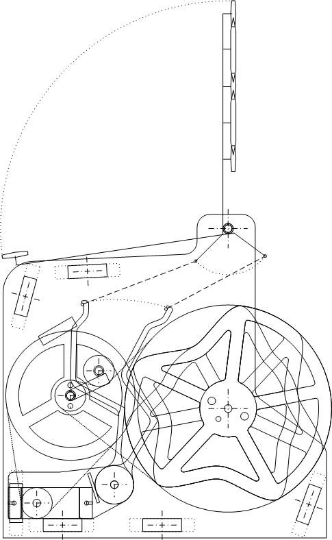
1. Structure examination
The blueprint is designed with 2D CAD. Each of parts are shaped by moving the arm parts on display to check confliction of structure.
Segment parts are fixed with wire and Segments’ arms are bent to avoid hitting other arms.
Each segment parts needs its own cam mechanism disc so 7 cam discs are designed.
When a cam discs move a arm, a arms recline, and then pulling a chain attaching to a wire of a segment parts so it makes a segment standing up to display number. When a arm goes back, segment parts go down because of it own weight.
。
2. Cam mechanism
The structure is made of 3mm thickness Acrylic.
Because of the mechanism mentioned above, the relevance between cam mechanism discs and arm parts is like below…
・When a arm tilt backward, a segment is displayed
→Position of cam disc : outer periphery
・When a arm tilt forward, a segment isn’t displayed
→Position of cam disc : inner periphery
Each segment named as a ~ g, the relevance between displayed number and segments becomes like below…
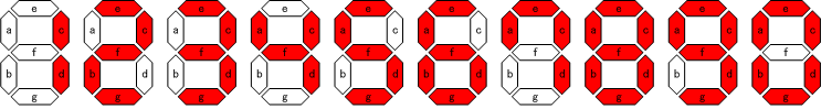
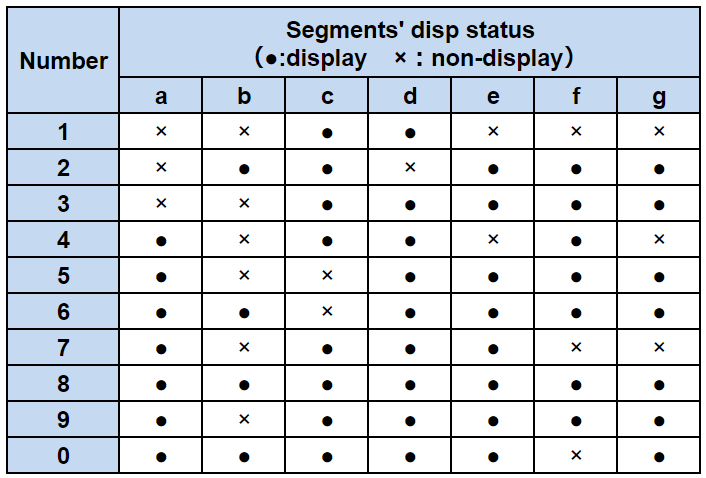
First, I divided a cam disc into ten equal parts and put point depending on the table above. If cell is ×, put a point on inner periphery OR if cell is ●, put a point on outer periphery. And then connect these points with line. That’s how I made my cam discs.
For weight reduction, lightening holes were cut out from discs. A center hole is for rotating shaft and other two hole is for fixing discs at same position so discs rotate in one body. And last smaller hole is made to discrime back and front side of disc.

* This time, we have simply cut out the meat for weight reduction, but in consideration of the load when rotating the arm when it is all assembled, it will be an appropriate center of gravity considering the load fluctuation when moving the arm So that the load on the motor should be minimized.
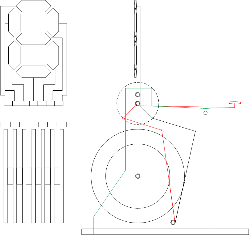
3.Arm structure
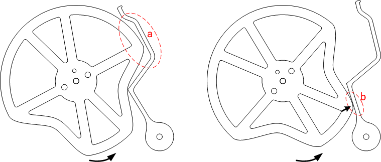
The arm is cut out from 5mm acrylic. I cut it at 2mm width to make contact with the cam. Since it is necessary to avoid hitting the next cam step, the shape is a square shape. (a)
The laser-cut cross section has a small step and the contact load between the cam and arm is large. Since the load is further increased because the segment is pulled when the arm descends backward, the flat part of the arm is pushed with a cam as shown in (b), so that the contact angle becomes as small as possible. Because of this structure, the cam rotates only in one direction and cannot be rotated backward.
If reverse rotation is not possible, for example, when displaying “1” from the “2” state, it is necessary to make one round, the efficiency is poor, but there is no problem because it matches the target “structure far from convenient”.
4. Power Transmission
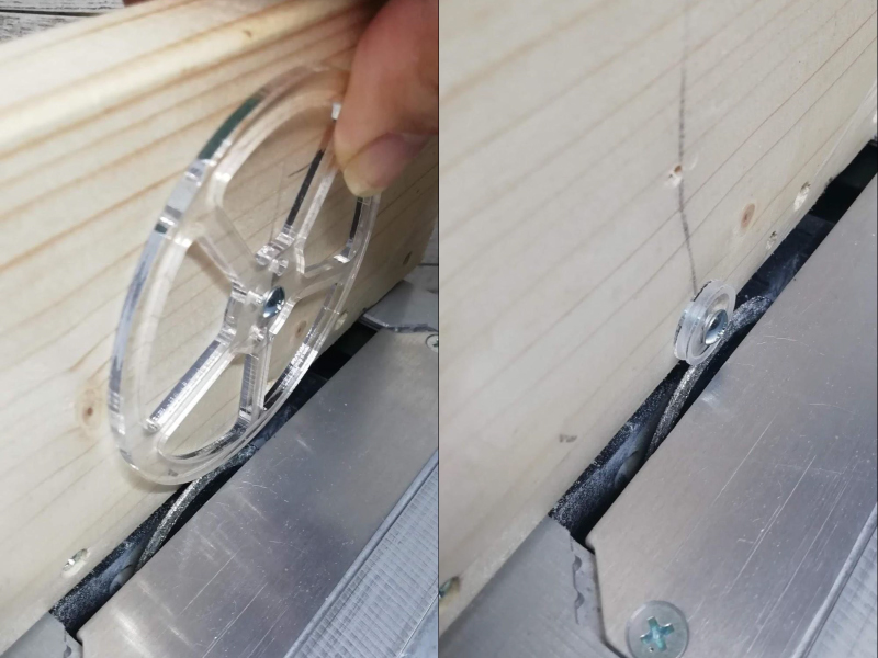
For power transmission, instead of gears, pulleys are used to simplify the structure. 3mm or 5mm acrylic plates were cut into a circle, dig a groove on the outer periphery, and make a pulley. Chains for jewelry are soldered to make loops to be use as the belt. Added a belt tensioner to prevent slipping. Total of pulley ratio is about 1:36 by using two pulleys of 1: 6.
It is also expected to prevent damage to the equipment by pulley will slip when excessive force is applied.
As shown below, the pulley groove is dug with a diamond cutter attached to a circular saw while fixing the disk and turning it by hand. Even with a 3mm acrylic board, it was easy to dig a groove.
The brass chain to be used as a belt is made into a ring by following procedure.
(1)Make the chain straight on a flat surface.
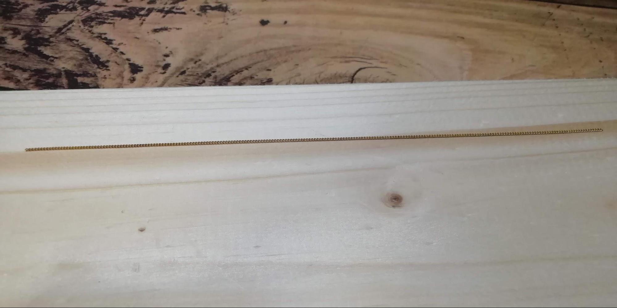
(2)Connect a thin copper wire (taken from loosen the copper twisted wire) to the chain at both ends.
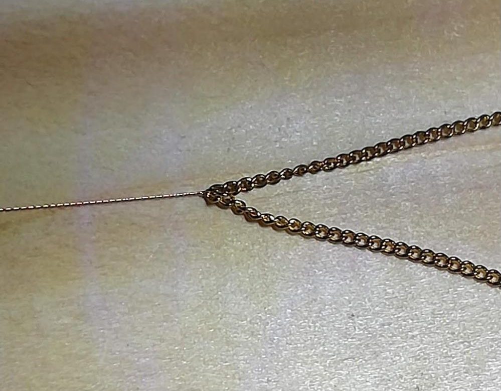
(3)Wrapped around a pliers handle and soldered with tension applied.
5. Segment part
Segments are created by cutting tin plates. After cutting, make it round and three-dimensional.
The wire, bent with pilier, was soldered to attach segment part. 3mm brass rods and 4mm brass pipes are used for the rotating parts. These brass bars and brass pipes are usually sold at any home center, but the accuracy is great, the clearance is almost zero, and there is no rattling but sliding perfectly. I strongly recommend this combination.
(In fact, since it is easy to wear with the same kind of metal, it should not be done like this, but if it is a easy going model, there is no heavy load, so I did it because of availability and ease of processing.)
The wire becomes straight when fixed with pliers and twisted with an electric drill. Also, the hardness increases bit more.
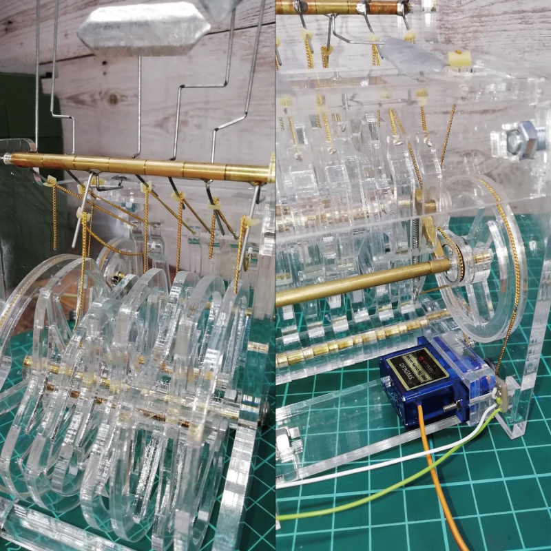
6. Assembly
Assemble each part.
The segment wires and arms are connected with a brass chain.
The chain is not easily entangled and hangs down under its own weight, making it easy to handle even near rotating parts. Also it looks good.
For connection, a rubber plate with a small cut hole is used.
Since it was necessary to adjust the length at last, this structure was adopted to make adjusting easier.
Also, it will come off before it breaks if excessive force is applied because it’s not fixed completely.
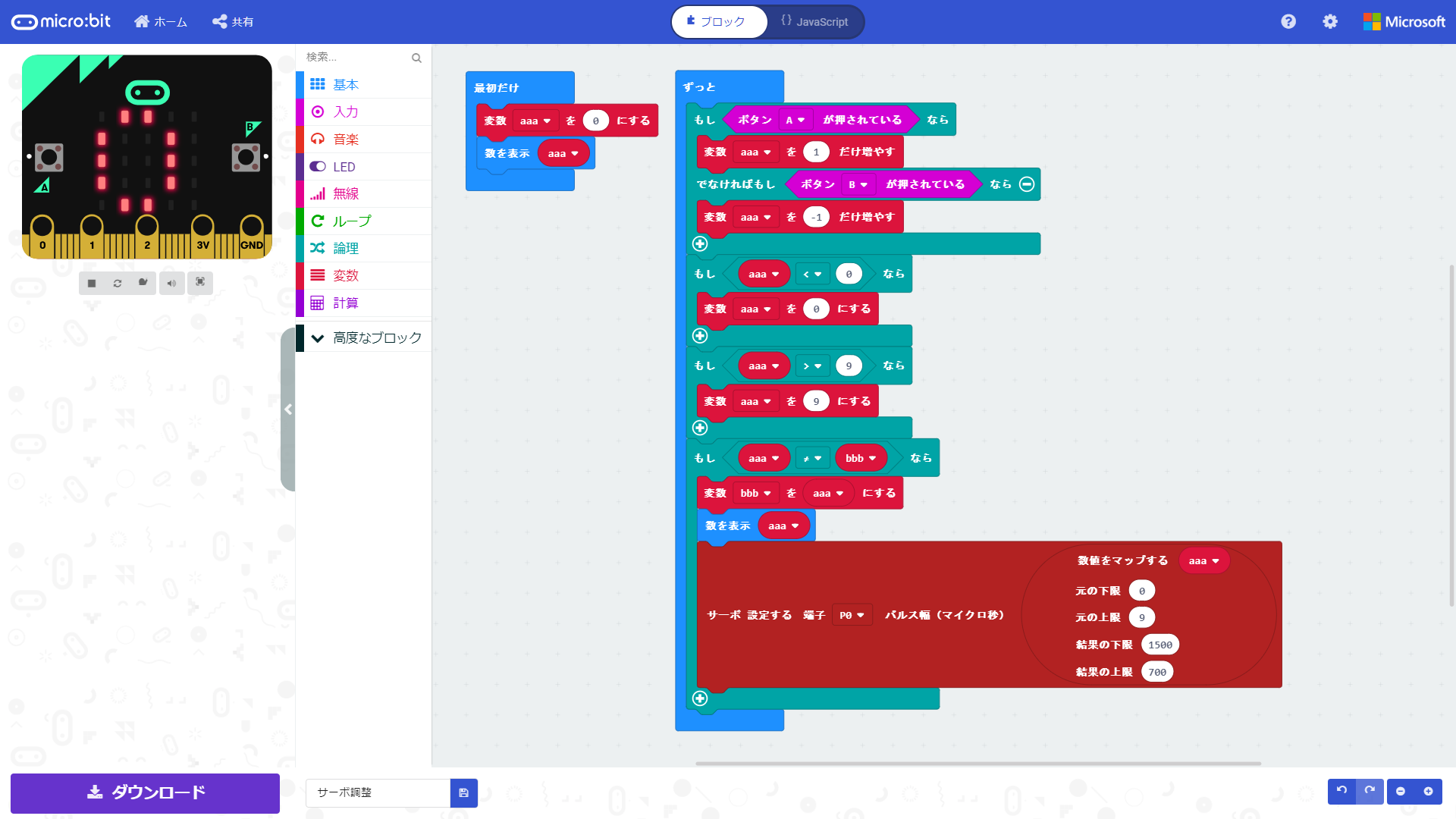
7. Programming
The servo motor which is used as power source is controlled by pulse signal.
And the signal generated by micro:bit connected with the servo.
By pushing A/B switch on micro:bit, pulse signal is changed to change rotation speed.
8. Complete !!! (still some part need bit more work though …)
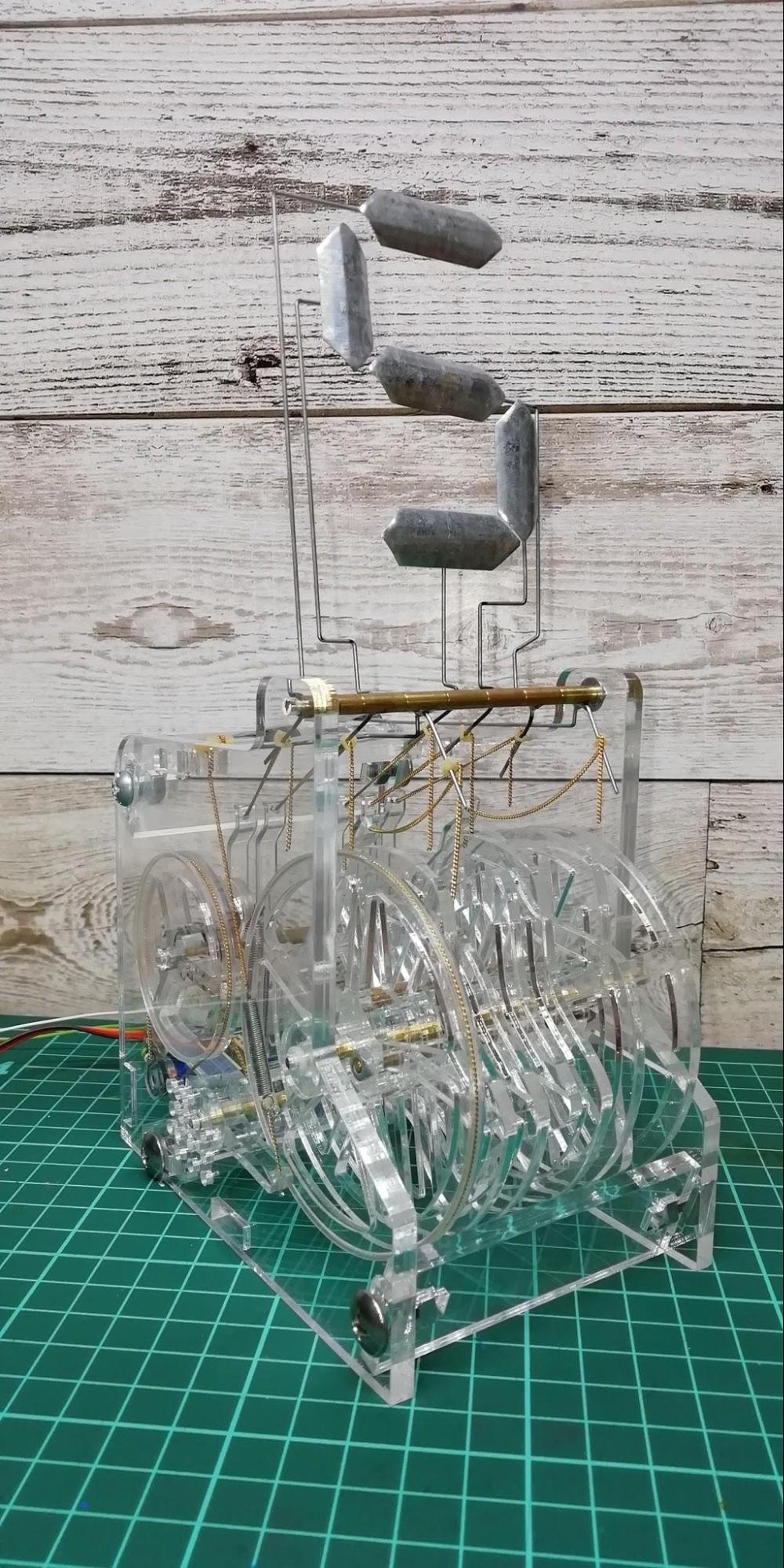
Here is also video showing how it works…
9. Future Work
To Complete this work…
Actually my work is not finished yet. Although it operates, it is not possible to specify an arbitrary number, and the number just keep changing continuously. For now, one of rules of the workshop, “(5)Speed of motor should be changed by input like value of sensors or time course.”, is not satisfied. To solve this problem, Some kind of position detection mechanism will be added so that rotation can be stopped at any number.
Additional plans…
・Create several additional units and perform operations (clocks, calendars, etc.) with multiple units.
・Control of the additional unit would be implemented with a wireless communication function using a BLE module instead of micro: bit.
・Control of the additional unit is equipped with a wireless communication function using a BLE module instead of micro: bit.
・Stop using acrylic and make everything from metal such as brass and copper.
・Make it as a kit so anyone can easily make it. (I would like to organize assembly workshops)